|
|
|
Tamiya Keen Hawk
and Dark Impact
By: Docnascar
Sorry about the popups. It’s a free site.
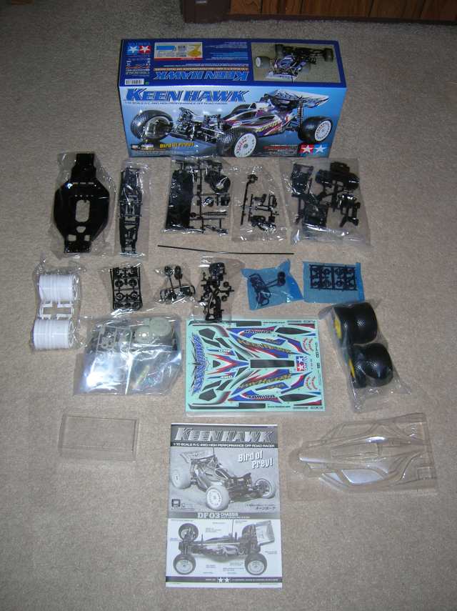
I
built my car without installing electronics during the build because I didn’t
have them at the time. So some pictures may not be exact but you should be able
to get the point.
Tips:
●
Parts Bags are not labeled but they are separated by contents and
labeled in the manual. Match the manual to the parts bags and label with a
black Sharpe.
●
Some of the plastic pieces have tabs on them with the letters. For
example Part V is in the blue bag and has a tab on it that says V
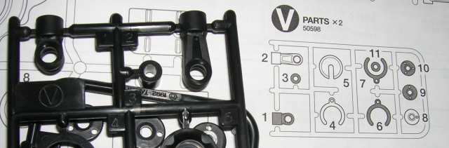
●
A and B are in the same bag
●
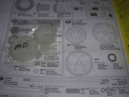
MT bag includes Gear Plate but there is no picture of it. It does
have it in the list.
●
Any time you snap a part off the holders be sure to clean off the
excess plastic on the part. This will cause some parts to bind if not cleaned
up. I used a cordless dremel with a stone but you could use sandpaper or a
file.
Step 2
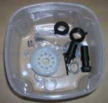
●
Get all your parts together from individual parts bags, for this
step of the build and put them in a container.
●
You'll notice each step has a list of parts on the left side of
the manual, this list can be used to check sizes of the parts as well. However,
sometimes the list does not contain all of the items for the step. You will
have to review each diagram to make sure you don't miss something.
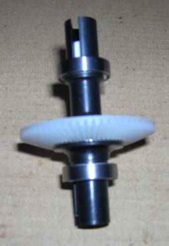
●
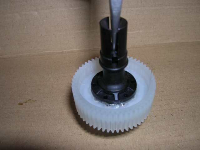
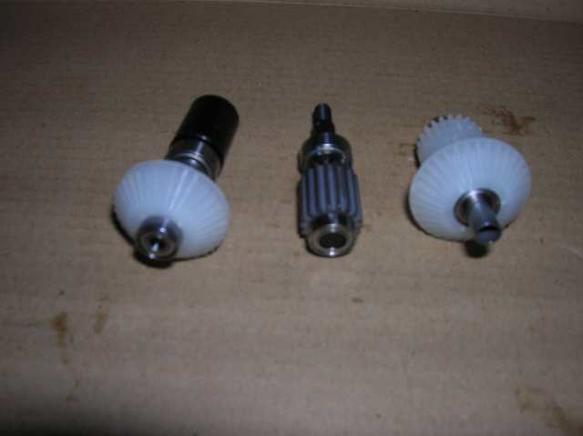
Be sure to allow the CA glue to dry on the diff joints prior to
connecting the diff joints to the diff gear and bearings. Otherwise you can CA
the bearings and they won't spin. Don’t get CA on the plate or the bearings
won’t spin freely.
●
Apply grease to MR5 (ball thrust bearing).
●
Push the two diff joints together by hand during assembly to seat
the bearings into the gear. You'll feel them pop into place.
●
When inserting MB7 (2mm lock nut) into D5, be sure the rounded
part of the nut is facing up in the top of D5.
●
Once you drop everything in onto the screw take a pair of tweezers
and push the lock nut assembly down.
●
Tighten the screw to the nut loosely so it won't fall apart. The
diff will hold the nut in place.
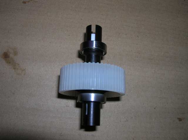
●
Adjust the diff, until the diff joints BEGIN to get stiff and has
SOME to LIGHT resistance (friction). The diff should have some resistance to it
when spinning the ends but not too much as too bind. Too loose is bad also.
DON'T OVER TIGHTEN!!!!
●
When installing the diff sponge, don't forget to cut the one in
half.
Step 3
●
Insert the diff assy. with the gear to the right when looking at
it with the same A1 orientation as the manual.
Step 4
●
Be careful not to use the MR2 bearing in place of the MR3 bearing.
The MR3's are a tad smaller and fit just right into the diff case bearing slot.
●
I placed the copper side of the MR4 bearing facing into the gears.
●
When assembly the e-ring use a pair of needle to push them on. The
washer goes between the e-ring and the bearing.
●
Tighten down MB4 into D3 with allen wrench
●
Apply the grease in step 5, its not as messy.
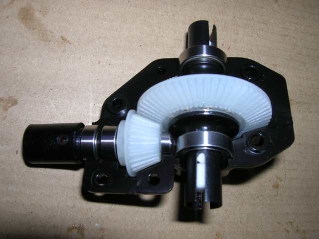
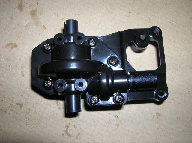
Step 5
●
Assemble case per directions.
●
Apply grease (not too much or the gears will bind) and spin gears a
few times in both directions to distribute the grease evenly.
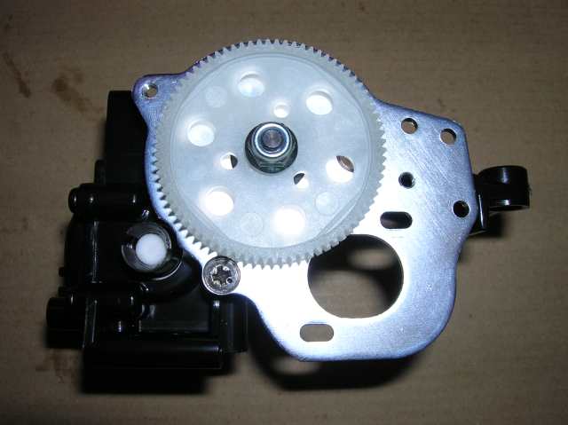
Step 6
●
Be careful not to use MA4 screws in place of MA3 screws. MA4's are
a little longer.
●
Don't forget the Spur Gear Bushing. MD4.
●
I waited to apply the grease until I installed my motor.
Step 7 and Step 8
●
Will install motor when it arrives
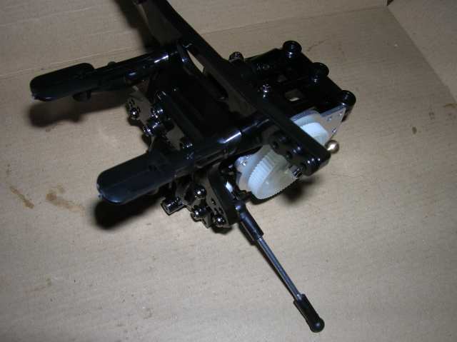
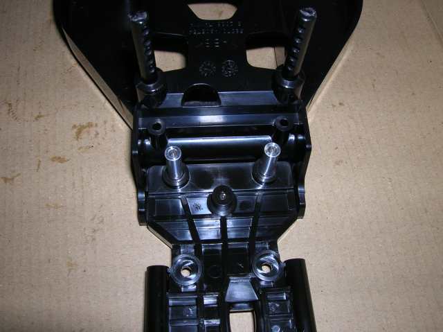
Step 9
●
Be careful not to strip the heads on the MA2 screws when
assembling the shock tower. The tower holes are not threaded and Tamiya has you
trying to tap holes with a machine screw. Its very hard to do.
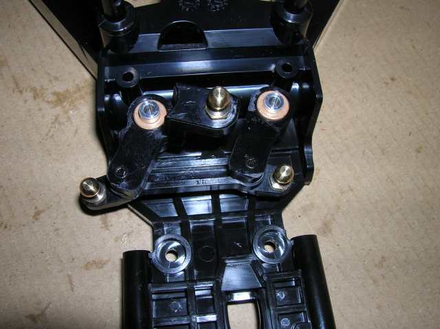
●
When building the rods I used two pair of pliers to twist the
adjustors on. They will even themselves out as you tighten them. Be sure to
start them straight.
●
You can use the manual as a guide for rod length. Make the two
rods as close as possible to the same size.
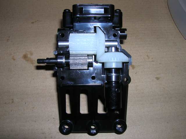
●
This pic, and following pics, don’t have M10 or the motor cover
installed. I was waiting for my motor to do that step but decided to install it
later. You can install it now.
Step 10
●
Use pliers again to push on c-clip, tweezers helps to hold c-clip
in place while your pressing it on.
●
Follow manual
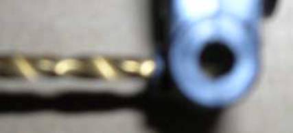
Step 11
●
You have to drill out the grub screw holes with a 2.5mm (3/32”)
drill bit. Use moderate drilling speed and little pressure. Let the bit do the
work, you don't want to pierce through the other side of the wheel hub when the
bit breaks through.
Step12
●
Run the MS4 parts back and forth through the D4 parts a few times
to clean excess plastic from the holes you drilled.
●
Be sure to put the hub on in the correct position.
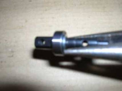
●
Mark one edge the shaft where the flat spot. Use this as a guide
to line up grub screw with shaft. Tighten the grub screws on the flat part of
the shafts, MC3 to MS4. Don't overtighten or you will strip the plastic. Once
you feel it touch give it a little pressure and stop.
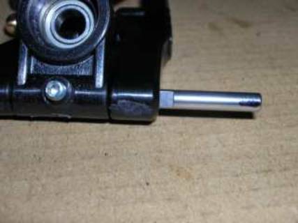
●
After you tightened the grub screw you can take the allen key and
push on the shaft from either side. You should feel the grub screw stopping it
from coming out. You know you tightened to flat part of the shaft this way.
●
Apply a little grease to both ends of the dog bones, MJ6, before
final assembly.
Step 13
●
Don't over tighten the MC2 screws, the plastic is weak at those
points.
Step 14
●
Same tips as in Step 2.
●
You will use less parts this time and the gear is the MH4 part.
●
Don't forget the diff grease on the bearings and the grease on the
thrust bearing.
Step 15
●
Be careful not to use the MR2 bearing in place of the MR3 bearing.
The MR3's are a tad smaller and fit just right into the diff case bearing slot.
●
When assembling the smaller gear assembly, don't forget to include
the MK5 washer.
●
Don't forget to apply grease to the gears.
●
Pay attention to screw placement on the cover.
Step 16
●
Easy step
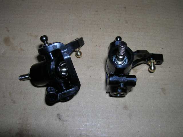
Step 17
●
Be sure to screw snap pin post facing in the proper direction
●
Don't over tighten the snap pin post, the plastic is very soft.
Step 18
●
When applying the bushing it was just as easy to grease the
steering post then slide the bushings on. Less mess.
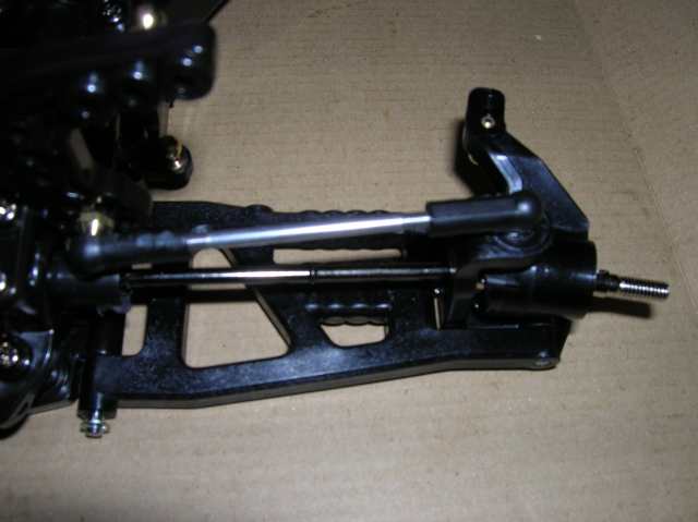
Step 19
●
Mount suspension arms in step 20 before step 19. Its easier to get
the e-rings on without the chasis in the way.
●
Use manual as a guide to rod lengths, make sure L and R are the
same length and note adjuster positions.
Step 20
●
Place one e-ring on each shaft prior to assembling. Then put it
together and clip on the other e-ring.
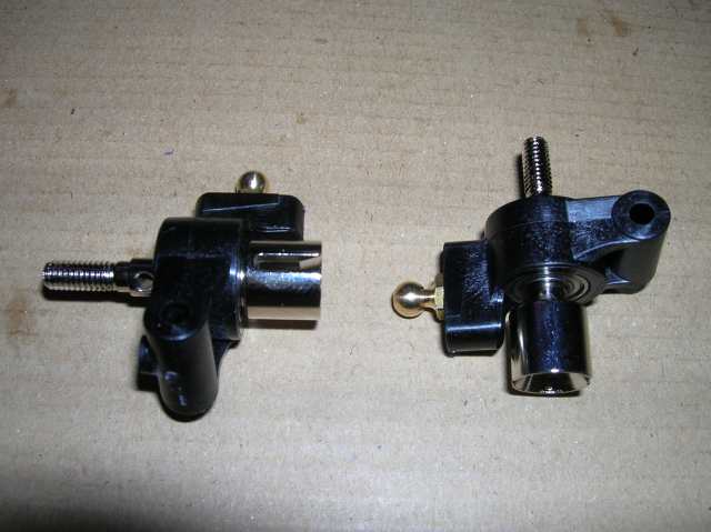
Step 21
●
Grub screw hole for D1 needs to be drilled with a 2.5mm (3/32)
drill bit. Follow same tips as Step 11.
●
Pre-thread C5 and C6 with the MD2 part, then take it apart and
assemble D1 to the C5 and C6 parts. When using needle nose pliers be careful
not to score the ball on the MD2. Try to to use the lip below the ball tighten.
●
Take note and don’t over tighten the MA4 screws. The C5 and C6
parts are very soft.
Step 22
●
Follow the tips in step 12 for the grub screws and shaft
alignment.
●
Grease the dog bones.
Step 23
●
Follow the manual
Step 24
●
Fill with oil to the edge
●
Remove all air bubbles the best you can
●
Make sure the lever is pulled completely down prior to putting the
cap
●
Shocks will slowly push themselves back out if pushed in after
assembling
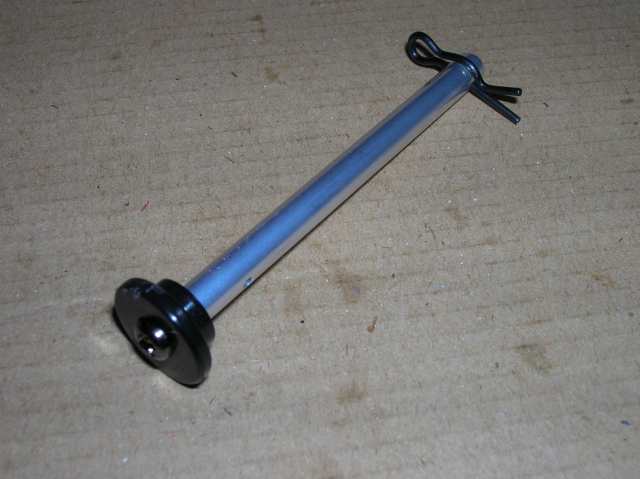
Step 25
●
Be sure X5 slips over the ball link shaft
Step 26
Step 27, 28, 29
●
Same as 23-25
Step 30
●
Don't forget to grease the bushings
●
Assembly the similar to the rear.
Step 35
●
Ensure lip of tire is in the valley of the rims made for the tire
lip as shown in the diagram of the manual
Step 36 and Step 37
●
Follow the manual
Step 37
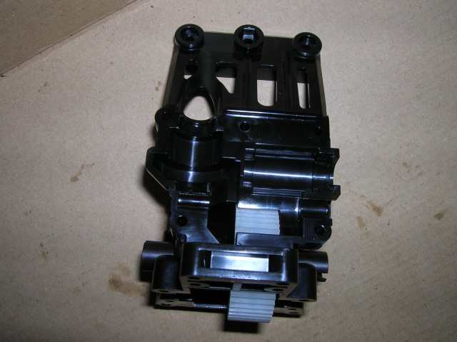
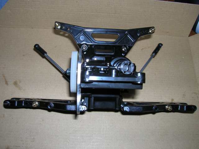
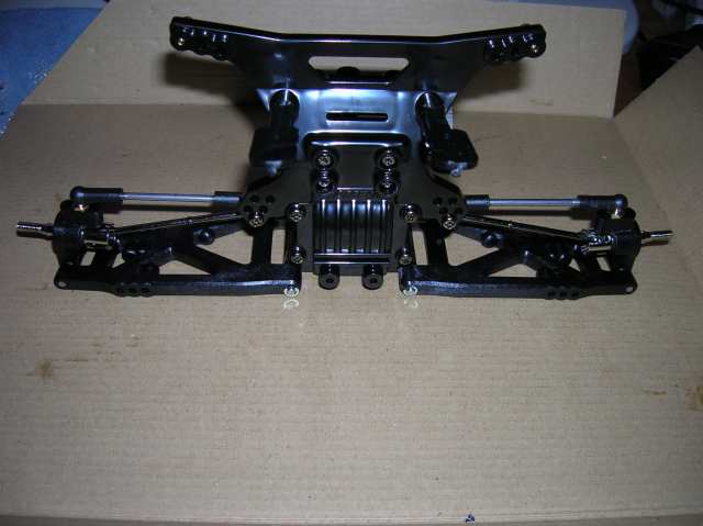
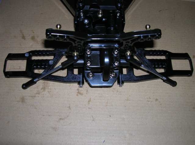
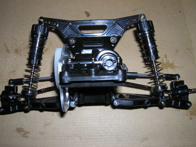
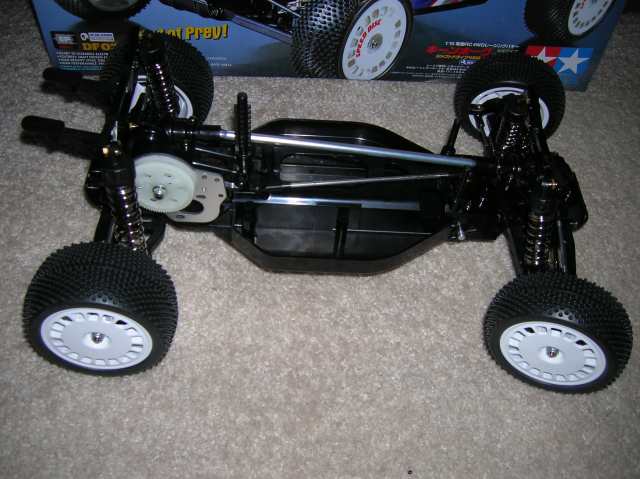
Step 38
Finished chassis with no electronics, hence no cover
for the motor yet.
I hope this helped someone.